Share on Facebook. A receiver tank Figure 6-1 stores energy for future use similar to a hydraulic accumulator.

Part 2 Reservoir Hydraulic Power Pack Basic Hydraulic Pneumatic Hindi English Youtube
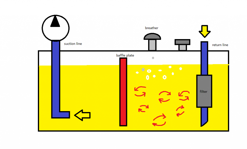
To help cool return fluid it should be.

. The excess reserve oil in a hydraulic system is to dissipate heat and prolong the life of the pump. Hydraulic design of baffles in disinfection control tanks. Movement of tanks under braking are explained.
As a rule of thumb for open tanks baffles should be of the same thickness as the tank shell but not less than 0125 for 1000 gallon tanks and smaller. A hydraulic liquid reservoir includes a tank that has a plurality of walls and a baffle structure which divides the inside of the tank into three compartments. Or 025 on larger tank sizes.
For a given footprint of a rectangular tank with a specified inlet width Winlet how does the hydraulic efficiency of a baffled tank depend on the configuration of internal baffles. In particular we address the key question. Most systems are normally designed for equipment operating at normal atmospheric pressure.
Baffle Support Methods that a customer might consider include. With the use of the perforated baffle design it is shown that the hydraulic efficiency of the tank can be improved from average to superior according to the baffling factor and the associated mixing in the proposed. This way the aerated oil stayed toward the top any particles that bypassed the filter stayed on the inlet side.
The optimal baffle design determined based on an analysis of energy dissipation in a single cycle of oscillations is presented. Baffles are long flat plates that attach to the inside of the tank to prevent swirling and promote top to bottom fluid movement. Furthermore large scale turbulent eddies shed by the perforations contribute to the mixing process in the chambers of the tank.
They are most commonly used for blending and solid suspensions because these applications often use vertical cylindrical tanks that tend to create swirling patterns regardless of the type of impeller being used. This includes hydraulic systems for truck or stationary installations. Mobile Equipment Reservoir Baffle Innovation.
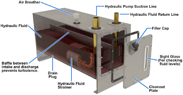
The standard baffle design parameters are as follows. Strip hangers welded to tank. This reservoir or tank may be a part of the framework of the main machine or maybe a separate stand-alone unit.
A good hydraulic reservoir should have internal baffles situated in such a way that they prevent return line air. A receiver tank is a pressure vessel and is constructed to pressure vessel standards. The drain D was dead center in the V- bottom.
Hydraulic oil in mobile equipment reservoirs has disturbances caused by the motion of the equipment. Hydraulic Reservoir System Design. Hydraulic reservoir accessories or hydraulic tank accessories can play a significant role in how well a hydraulic reservoir performs and to what degree fluid cleanliness is maintained.
Poor tank design can greatly reduce the efficiency of a well-designed hydraulic system. With the use of the perforated baffle design it is shown that the hydraulic efficiency of the tank can be improved from average to superior according to the baffling factor and the associated. I am working on a firewood processor and am looking to build a hydraulic tank.
Over sizing the reservoir by 5 to 15 gallons will offer substantial benefits by allowing the hydraulic system to run cooler and extending the life of the systems pump. Journal of Hydraulic ResearchDe Recherches Hydrauliques 400-407. By Gary Alexander CFPHS.
I had some questions in particular about baffle design. Furthermore large scale turbulent eddies shed by the perforations contribute to the mixing process in the chambers of the tank. Reservoirs are of two general types - non-pressurized and pressurized.
This study focuses on understanding the hydraulic design of baffled contact tanks using computational fluid dynamics simulations. Baffle skip welded to tank wall with gussets welded behind it. Number of Baffles and Baffle Width.
H Carlston J Venayagamoorthy S. An inlet is connected to one lower compartment while an outlet is connected to the second lower compartment and a third upper compartment is interconnected with both the first and second lower compartments at a. A hydraulic reservoir does not only provide a place to put.
To avoid air. At the end of the work cycle the air is simply returned to the atmosphere. The baffle ran the length of the v-bottom tank slightly offset from the center.
Air entrainment must be avoided in any hydraulic system. In this article sloshing is illustrated. Locate the inlet tube under a substantial depth of oil to avoid vortexes or add vanes to the throat of the tube extending outward.
In both cases the design of the reservoir and implementation play an important role. Baffle Off Wall Dimension. Fluid disturbances are commonly called sloshing and cause a number of issues such as breather damage short-circuiting diffusion and entrainment.
At the end opposite the return there were 2 15 dia holes Hlocated about 3 and 6 from the bottom. The store will not work correctly in the case when cookies are disabled. Hydraulic design of baffles in disinfection control tanks.
With the use of the perforated baffle design it is shown that the hydraulic efficiency of the tank can be improved from average to superior according to the baffling factor and the associated mixing in the proposed. That is up to 515 GPM. Custom Hydraulic Tank Complex Fabrication Design Manufacture.
Power response and flow response is always carried out in a vessel that has four standard width baffles width 112th of the tank diameter. Propower manufactures non-pressurized hydraulic reservoirs and pressurized reservoirs operating up to 5 psi. This is possible because air is a gas and thus is compressible.
Index Termsroad tanker computer modeling liquid oscillations equivalent models baffles energy dissipation. The processor will have a 17 GPM saw pump 65 GPM pump for misc cylinders and a 287 GPM 2 stage pump for the splitter. This study focuses on understanding the hydraulic design of baffled contact tanks using computational fluid dynamics simulations.
Hydraulic design of baffles in disinfection control tanks. The default number of baffles is four 4. Baffles direct diffuse and contain fluid and increase tank stiffness Fig.
In particular we address the key question.

Why The Tank May Well Be A Hydraulic Fluid S Best Friend

Novel Slot Baffle Design To Improve Mixing Efficiency And Reduce Cost Of Disinfection In Drinking Water Treatment Journal Of Environmental Engineering Vol 143 No 9
Reservoirs Strainers Filters And Accumulators Engineering Library

Industrial Hydraulics Design Hydraulic Reservoir Design
Hydraulic Tank Design And Work Basic Stuffworking Com
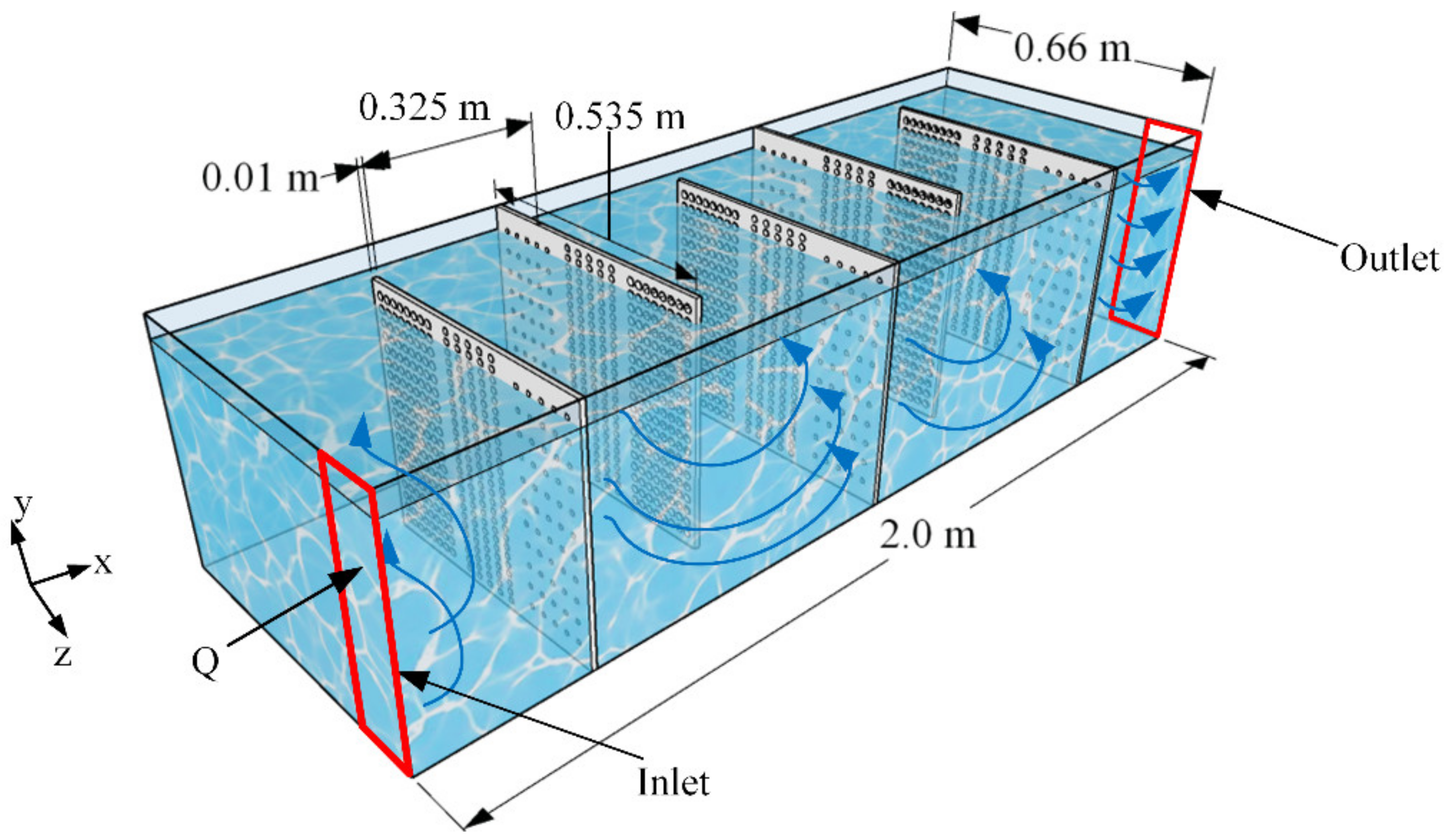
Water Free Full Text A Perforated Baffle Design To Improve Mixing In Contact Tanks Html
Hydraulic Tank Design And Work Basic Stuffworking Com

Hydraulic Tank Design And Work Basic Stuffworking Com
0 comments
Post a Comment